How SOLIDWORKS, Inventor, Creo, and NX files become photorealistic marketing visuals. A practical guide for engineering teams handing off CAD to visualization studios — and for marketing managers who want to understand what's happening to their company's files.
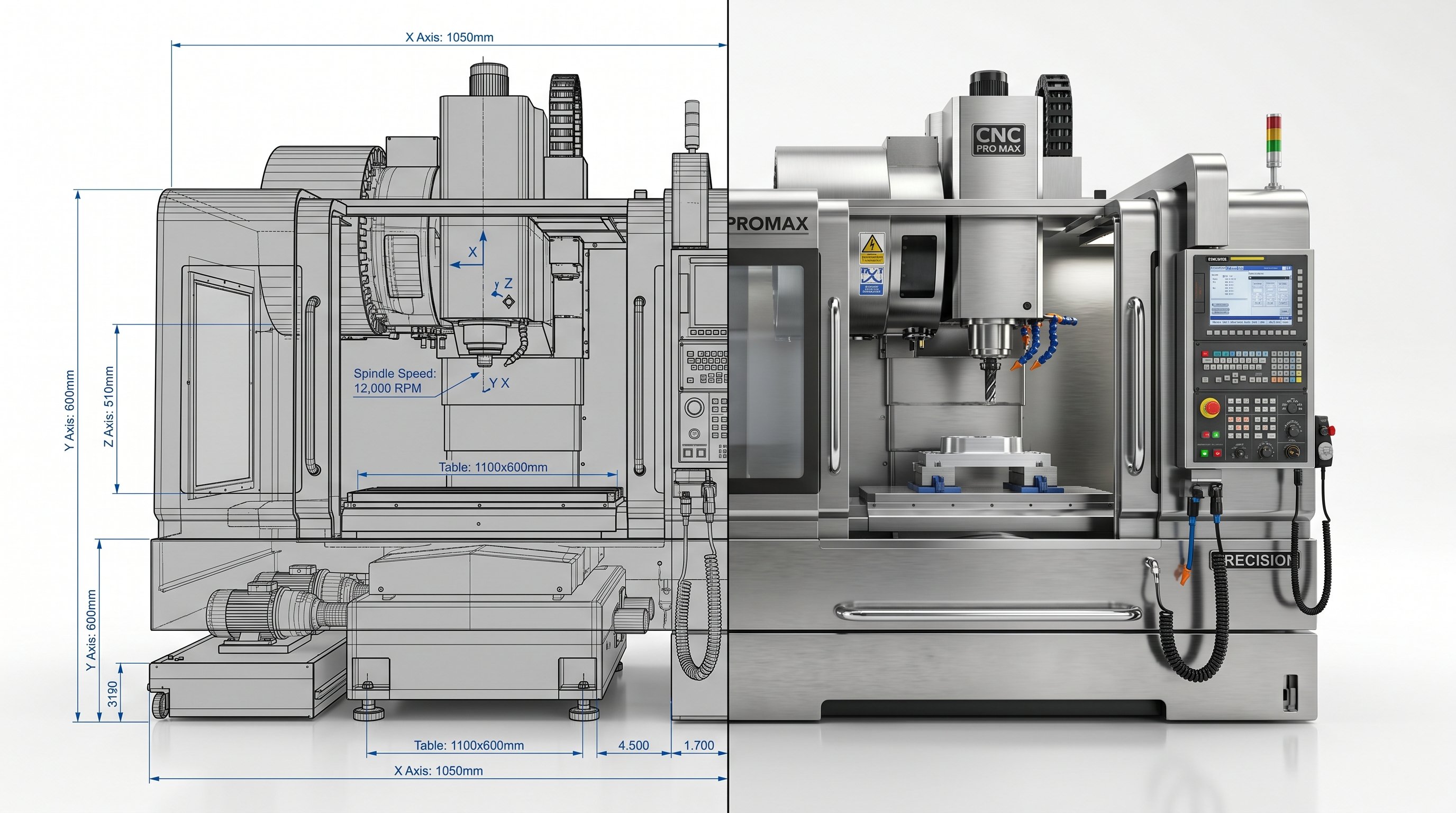
A mechanical engineer once sent us a SOLIDWORKS assembly of a 5-axis machining center — 3,400 parts, 18 GB of geometry, fully parametric, every tolerance perfect. It had taken his team six months to model. When we opened it in our rendering pipeline, we had to rebuild 60% of it before a single marketing visual could be produced. Not because the CAD was wrong — because engineering CAD and marketing visualization are solving different problems with the same geometry.
This gap — between how engineers build models and what rendering studios need — is where most industrial CAD-to-marketing workflows lose time and money. This article walks through the full pipeline, what each step costs in time, and what both engineers and marketing managers should know before their next project handoff.
Engineering CAD is built for manufacturing precision. Every feature exists because it will be machined, assembled, or tolerance-checked. Photorealistic rendering is built for visual convincingness — edges need subtle bevels, surfaces need micro-roughness, and materials need weathering maps. A new machine looks fake on camera without subtle imperfection.
These two paradigms don't map cleanly onto each other. A "correct" CAD model is almost never a "correct" render-ready model, and converting between them is where the real production work lives.
Every industrial visualization project follows these stages in sequence — the proportion of time changes, the order never does.
The single most important choice in the pipeline is made at export. The two formats that work reliably are:
Universal standard. Preserves precise geometry, assembly hierarchy. Read by virtually every 3D application. Always the first choice when native files can't be shared.
SolidWorks .sldasm, Inventor .iam, Creo .prt, NX .prt, Fusion .f3d. Preserves feature history, appearances, mate relationships. Best if studio has matching license.
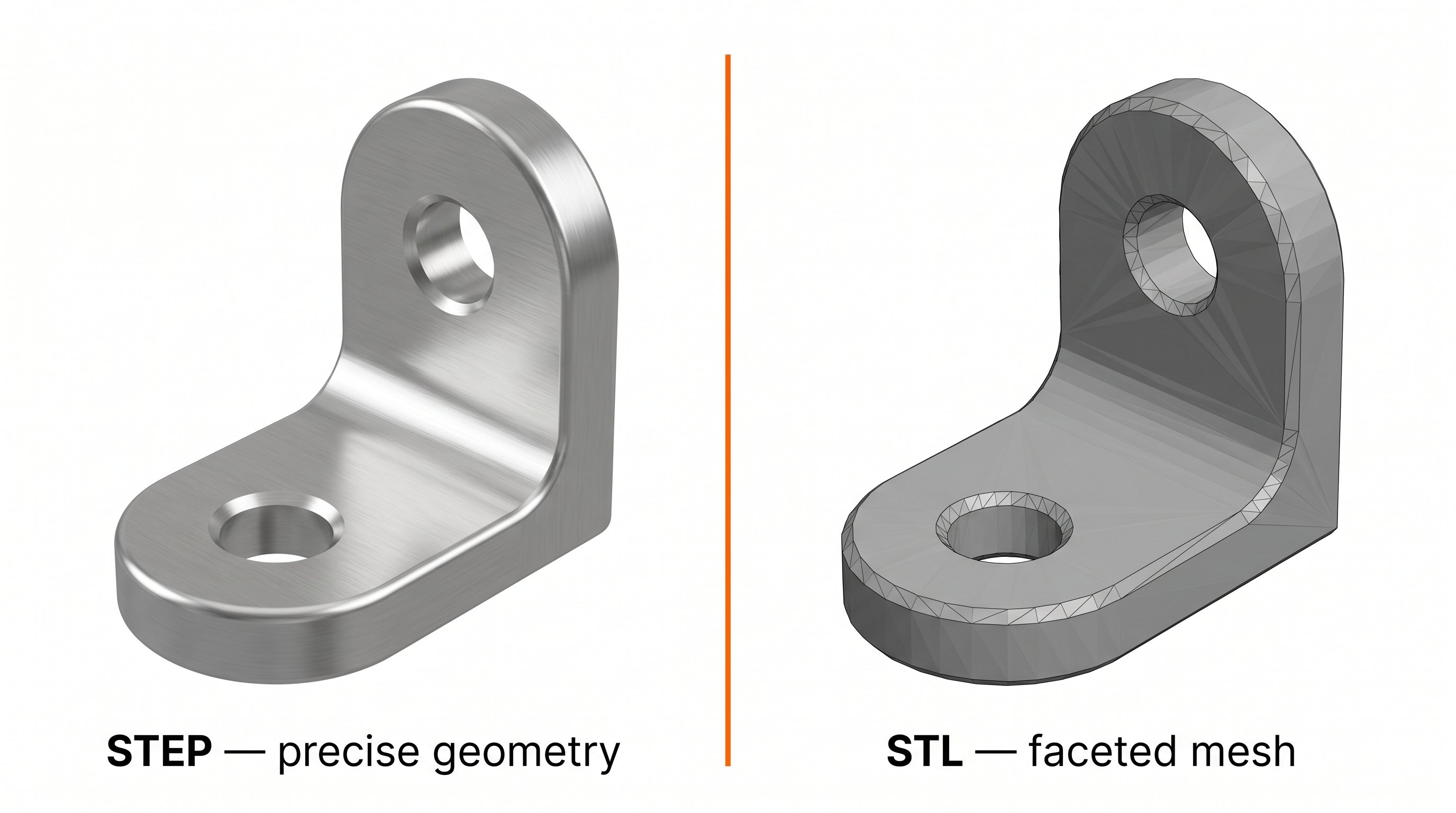
Mesh format for 3D printing. Triangulates at fixed resolution — visible faceting on curves. Usable only as last resort; requires full remodeling of affected surfaces.
Still lossy mesh formats. OBJ works for simple parts only. 3D PDF and DWF are not rendering-ready in any practical sense for industrial assemblies.
Even clean CAD files contain elements that cause problems when rendered: hidden internal components that will never be seen on camera, redundant mirror parts, and unresolved feature errors inherited from the design phase. On a well-organized SOLIDWORKS assembly, this takes 2–6 hours. On a poorly structured inherited file, it can take 2–3 days.
CAD assembly hierarchy follows manufacturing logic. Rendering hierarchy needs to follow animation logic: what moves together, what stays fixed, what appears or disappears during a sequence. For exploded-view animations or cross-section reveals, the hierarchy has to be completely restructured before animation starts.
CAD geometry has no UV coordinates — no built-in map telling materials where to apply to the surface. For a complex industrial product, UV unwrapping can take 4–16 hours of dedicated work. Studios increasingly use automated UV tools (RizomUV, Houdini auto-UV) that dramatically reduce this time for hard-surface geometry.
This is where CAD visuals become photorealistic renders. Each surface needs a physically-based rendering material — a set of texture maps that control how light interacts with the surface.
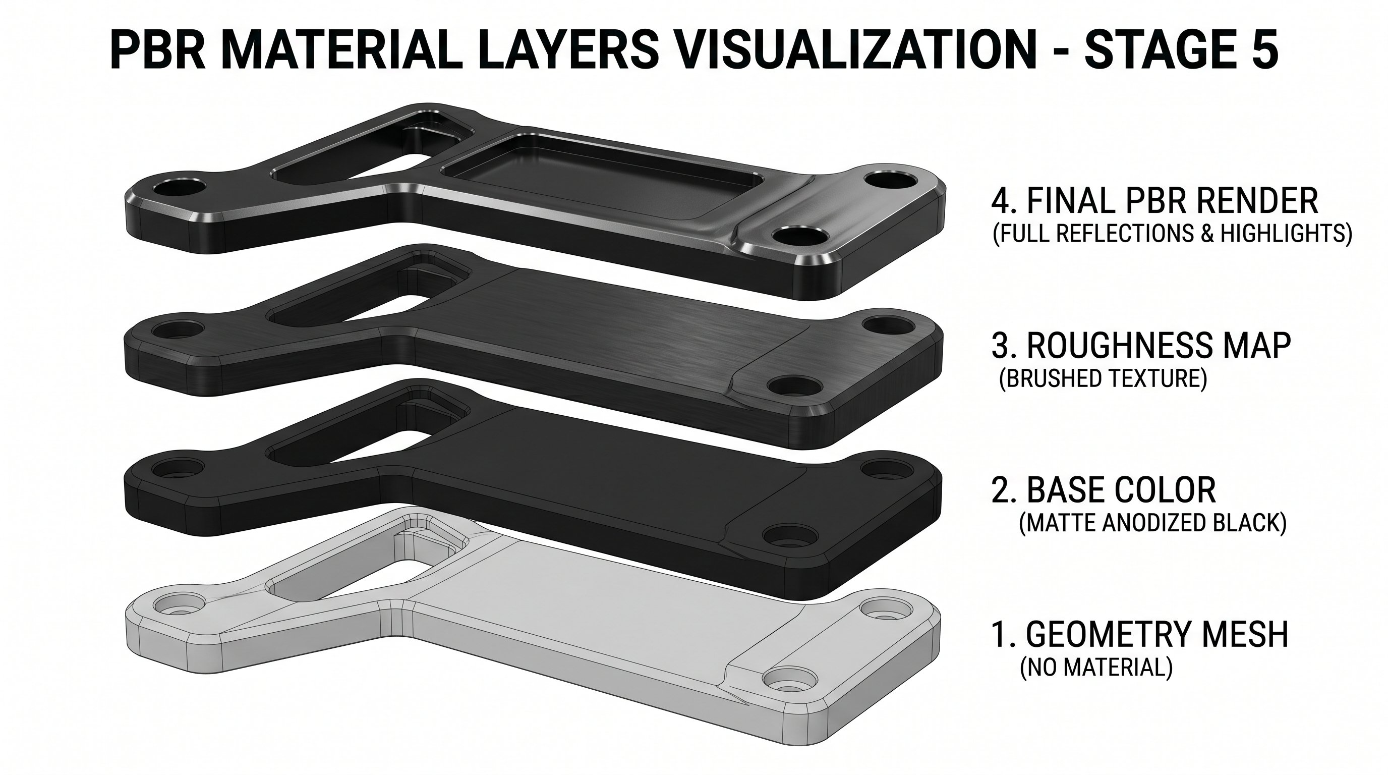
Professional rendering studios maintain extensive PBR libraries — we use a library of 400+ calibrated materials specific to industrial surfaces (anodized aluminum in six different textures, stainless steel grades, medical-grade ABS, powder-coated RAL colors) so a new project doesn't start material creation from scratch.
Lighting is where rendered images stop looking like CAD and start looking like product photography.
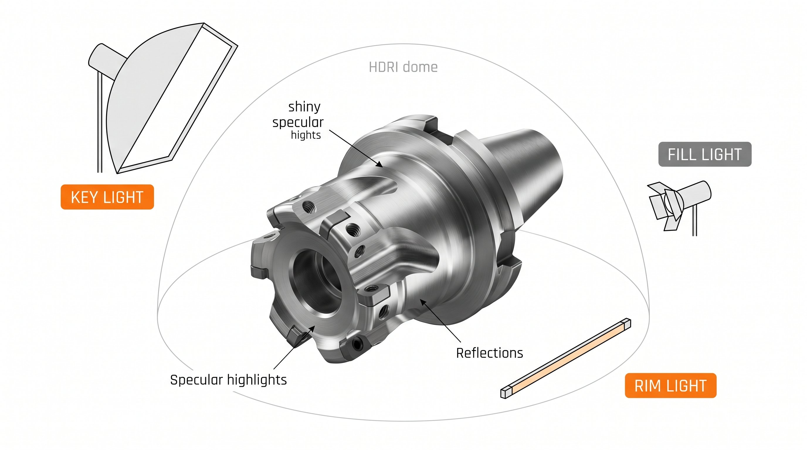
For technical and industrial renders, this typically means: an HDRI environment for realistic ambient light reflection, 2–4 area lights for primary illumination, edge lights to separate the product from the background, and often a subtle "product highlight" light that gives key surfaces the reflective shine associated with premium industrial design.
Rendering itself — the pixel-by-pixel calculation of how light bounces through the scene — happens in one of a small number of professional render engines. For animation, this scales to potentially hundreds of CPU-hours per finished second. Modelight uses infrastructure with 2,000+ processors available in parallel, which makes the difference between "ready overnight" and "ready in three weeks."
A few habits in your CAD process dramatically reduce downstream time and cost at the visualization studio.
Got CAD files ready for visualization? Send us your STEP or native format — we'll come back with a realistic preparation timeline and production quote within 24 hours. We handle SOLIDWORKS, Inventor, Creo, NX, CATIA, and Fusion 360. Send files for quote →
The best formats are STEP (ISO 10303) and native parametric files from SolidWorks, Inventor, Creo, NX, or Fusion 360. STEP preserves precise geometry and is universally supported. Mesh formats like STL should be avoided — they lose geometric precision and require significant cleanup before rendering.
SOLIDWORKS Visualize produces quick technical renders useful for internal reviews and engineering documentation. For marketing visuals — website hero images, trade show animations, broadcast-quality films — dedicated studios using Blender Cycles, V-Ray, Corona, or Arnold produce substantially higher visual quality suitable for external publication.
CAD geometry is mathematically precise but visually sterile — it lacks micro-surface imperfections, material weathering, and edge detailing that make objects look real. Professional photorealistic rendering adds PBR materials with roughness maps, normal maps, and subtle wear. Without this layer, even a perfectly modeled CNC machine will look like a computer-generated toy.
For a clean STEP file of a moderately complex industrial product (500–2,000 parts), the CAD-to-render preparation typically takes 1–3 days before visual work begins. This includes geometry cleanup, hierarchy reorganization, UV mapping, and removal of internal components. Messy files or STL meshes can extend this to 1–2 weeks.
Usually no — professional studios prefer full-detail CAD files and perform simplification themselves, because they know which components need to remain visually detailed for the final shot. However, if your CAD contains confidential internal components, it's reasonable to remove or replace those before handoff. Always discuss IP concerns upfront.
Drop us a STEP file or native CAD, tell us what you need — and you'll have a realistic scope and quote within one business day.
Send CAD for quote